Inexpensive rotary encoder
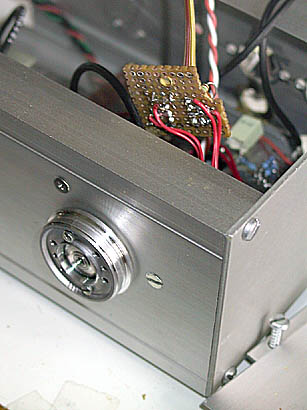
 - get a dead harddisk, preferrably an older one
- take out the flat spindle motor which spins the HD platters
- connect wires to two different motor output leads (any)
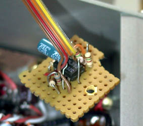
- build this circuit:
(Resistor values aren't critical - junk box parts. LM393 is a cheap dual comparator)
The circuit outputs are high as default. When the spindle is turned, there will be pulses on the outputs. The lower square wave output signal leads or lags 90 degrees in respect to the upper signal - it depends on the direction the spindle is turned. The circuit works from 2V up to 36V, so 3.3V logic works too. The LM393 gives out good pulses with as little as 5mV differential input, which means that this circuit works even when the motor is turned very slowly.
A HD stepper/spindle motor is ideally suited as an encoder because it isn't bulky nor noisy, and it can be spun easily (doesn't "brake" and carries good momentum), just like commercial units. And, it doesn't cost anything.
For a similar setup with example source code, see: Rotary encoders using stepper motors (Richard Hosking, VK6BRO)
 To be of more use, the phase shift encoded signal is usually decoded into two
logic signals e.g. 'UP' and 'DOWN'. This can be done with a bunch of discrete
flip-flops. For example if you turn the wheel clockwise, the 'UP' signal is
pulsed on each step. If counterclockwise, the 'DOWN' signal is pulsed at each
step. An example of a discrete decoder can be found in a post in the nativeinstruments.de
forum. I also took the liberty of mirroring Dr BeaT's schematic
here, in case the forum goes down. Note that I haven't checked if the circuit
works 100%, but I've heard it works ;-), and to me it looks quite convincingly
like it is going to work.
To be of more use, the phase shift encoded signal is usually decoded into two
logic signals e.g. 'UP' and 'DOWN'. This can be done with a bunch of discrete
flip-flops. For example if you turn the wheel clockwise, the 'UP' signal is
pulsed on each step. If counterclockwise, the 'DOWN' signal is pulsed at each
step. An example of a discrete decoder can be found in a post in the nativeinstruments.de
forum. I also took the liberty of mirroring Dr BeaT's schematic
here, in case the forum goes down. Note that I haven't checked if the circuit
works 100%, but I've heard it works ;-), and to me it looks quite convincingly
like it is going to work.There also exist dedicated 'quadrature decoder' chips that can be used. But, they often contain a multi-bit counter register in addition to UP/DOWN outputs, together with a load of other features, and are quite expensive. If you don't need UP/DOWN pulses and need just to maintain the number of times the wheel was jogged in some direction, then a simple 4-bit or similar counter may be sufficient. This means you can use one of the many bidirectional synchronous or asynchronous counters (aka Up/Down Counters) available, like e.g. a 74LS669: one signal is fed to both CLK and RCO to create the count, the other to U/!D to specify the counting direction.
On the other hand, if you are already using a microprocessor in your system, decoding and possible wheel debouncing is very easy to perform in software completely. Here is some example code for the MSP430 series:
// Port P2.0: wheel control
// Wheel encoder signal outputs go to port 2 pins 2.0 and 2.1,
// with interrupt enabled on pin 2.0

#include <msp430x14x.h>


// -- global counter for wheel steps

volatile signed int wheel_counter;


// -- port 2 interrupt handler

interrupt[PORT2_VECTOR] void intPort2(void) {

  // get pin 2.1 state
  int tmp = P2IN & BIT2;

  // interrupt caused by port pin 2.0?
  if(P2IFG &= BIT0) { // (simultaneously, reset other interrupt flags)
      // pin 2.0 is low, so the state of pin 2.1
      // determines which way the wheel was turned:
      //   1=up, 0=down
      // currently the counter is changed by +-1, but of course this
      // can be modified (for example, for a 'Fast Scan' button
      // in the circuit)

     if( (0!=tmp) && (wheel_counter<32000) )
     {   wheel_counter += 1;  }
     else if( (0==tmp) && (wheel_counter>-32000) )
     {   wheel_counter -= 1;  }
  }

  // reset interrupt flags (actually, bit0, if it was set)
  P2IFG = 0x00;
}


// -- init

void initInterrupts(void) {

  // enable tuning wheel interrupt on pin 2.0 (more info in
  // MSP430F14x series users guide, page 135)
  P2SEL &= ~(BIT0+BIT1);      // don't use modules, just i/o
  P2DIR &= ~(BIT0+BIT1);      // set both 2.0 and 2.1 to inputs
  P2IES |= BIT0;              // 2.0 high->low generates interrupt
  P2IFG |= 0x00;              // clear interrupt flags

  // reset the step counter
  wheel_counter = 0;

  // enable interrupts (users guide page 47, table 3-5)
  P2IE  |= BIT0;              // pin 2.0 int enable
  IE1 |= NMIIE;
  _EINT();
}
The idea basically is: connect the two encoder data lines to two input pins of your microcontroller/processor, set one pin to cause an interrupt at rising (or falling) edges of the incoming signal, and in the interrupt handler check the state (high or low) of the other pin. If your uC doesn't offer interrupts on input data pins, you'll have to use polling which is less efficient. E.g. you'll have to set a function or task to regularly (in short enough intervals) check the state of the first pin. If its state changes, check the current state of the other pin, and increment/decrement your counter accordingly. Of course, detect only one state change direction e.g. low->high and skip high->low, otherwise it counts e.g. up and then immediately down again and the counter remains zero.
(C) 2003 Jan Florian Wagner, OH2GHR